
The power of controlling power…
Interacting with the outside world is one of the most exciting aspects of programming RaspberryPIs and Arduinos. Whether you want to turn on a motor, control an air pump or activate a solenoid – all of these require using the tiny amounts of current from your pins as switches to control large amounts of current needed by these demanding electro-magnets. Enter the fantastic, incredible, transistor…
But not any transistor – this one is incredible for heavy draw devices – it is the N-Channel, Logic Level Mosfet. Otherwise lovingly called “FQP30N06L” or “RFP30N06LE” by their respective makers. An example is pictured above.
Why can’t I just power my motor with the pins on the PI/Arduino?
It turns out the transistors hidden inside the processor for your device are tiny. So tiny, that if you try to power a large device with them they’ll melt like the thinnest of fuses. When they melt it ruins your device.
Solenoids, motors, and electromagnetic devices require LOTS of power. They need that power to create a large enough magnetic field to pull on their turny-bits or pulling-bits. That power cannot be run through a tiny little transistor hidden deeply in your processor. Instead we take it through the BEEFY path available inside this POWER-MOSFET.
What can I control?
These things are VERY capable little devices. They can control lots of stuff, that you, as the hobbyist shouldn’t attempt. So…
No Mains!!! (a.k.a. stuff that runs at 110V or greater)
For anything connected to mains take a look at some of my other articles that provide a safe, tested means of controlling mains power. Everything we do with transistors, should only work on low voltage systems, like stuff at 12V or 5V or lower.
Articles for controlling mains…
Raspberry PI Controlling Power through GPIO (no wifi needed)
Raspberry PI for controlling TP-Link POWER
Raspberry PI for Controlling Wemo Power
How to wire these puppies up…

The important part about using these transistors is in making sure the “load” or the thing you are trying to control – is wired in before the transistor’s control. Meaning, the transistor should be gating whether or not electrons can “leave” the device and make it to the ground (0V). As in the picture above where the GPIO is going to be one of the pins on your PI or Arduino, and the “Load” is the motor or solenoid.
Look at this image:
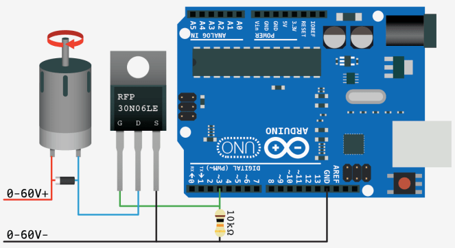
See the little “G”, that corresponds to the “g” in the schematic image above this image. The “d”, and “s” as well also match the schematic. In this graphic from (bildr.org). Note that pin 3 on the Arduino is the one controlling whether or not the electrons coming from the Motor, will be able to leave the the “s” to get to their 0 or Negative terminal.
The other thing to take note of is the high-value resistor(any large value will do) between the pin, and ground. That is very important. Without it, the electrons available from your pin, which you are sending out from the PI or arduino, will take a long time to leave the “g” or “gate” of the mosfet, and sit-around keeping the mosfet “on” longer than you intend.
Where to get these little guys…
Lots of folks sell them. They shouldn’t cost you more than $1. Sparkfun is an easy place to get them. If you want to buy in bulk – check out digikey.com or mouser.com.
https://www.sparkfun.com/products/10213
Turning them on and off.
I have an article on this already! Once you setup your circuit, you can switch the transistor, by simply turning on and off a pin. Specifically, the pin wired up to the “g” or gate of the transistor. Please see:
Raspberry PI3 NodeJS GPIO Control: rpi-gpio
Have fun! Let me know what you wire up in the comments below!
