Most people don’t understand the low-level fundamentals of computers.

Computers are made from transistors… a ton of them.
When you start in on your computers science degree, the first thing you learn is programming languages, algorithms, computer architecture and the beginnings of networking. These are all VERY high level abstractions of what is happening inside the computer. Most computers-scientists actually have no clue how the computer functions at the lowest levels.
You, humble blogger-brothers reader, should not be so uninformed. 😉
So this little series starts at the very bottom… as opposed to computers science – that starts at those higher level abstractions. We’ll get there to “point” at those topics – but there are a ton of resources that talk about those higher level concepts.
People “know” computers are made of billions of transistors… but they don’t know how.
So lets dive in…
The first building block… the transistor.
That is the design of the first transistor. The materials are huge in this one – but it kicked off a revolution. It made it possible for purely germanium/silicon based materials to control the flow of electrons – kinda like a controllable switch. Before these guys – very, very power hungry “heater-based” vacuum tubes (glass and metal beauties) were required. To read more of that history… this article has a nice timeline: History of the Transistor
It actually uses force fields… checkout this picture:

That purple-whitish bit – gets filled with an electron “field” that allows electrons “flow” from D to S. That B guy is the body – used for taking the heat – or just holding it all together. This is a subject of study all on its own… but its awesome. Checkout videos on MOSFETS.
Anyway…
With the advent of the transistor… and a “little bit” more work it became possible to “print” transistors into plates of silicon through exposure of UV-light lithography. You can see a little of that at this article: here
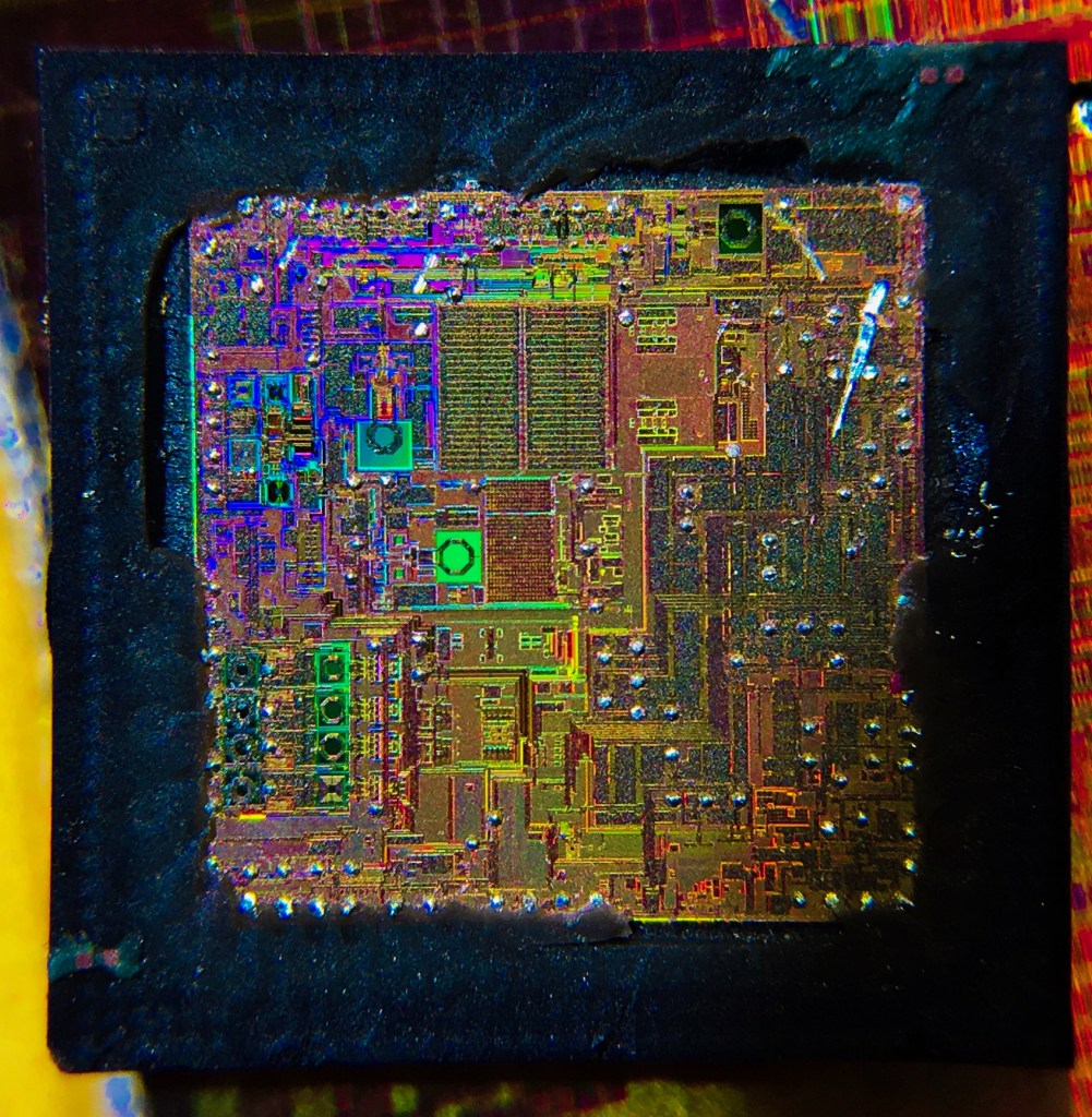
Once you can do this printing – it suddenly becomes possible to start linking millions of these little guys together into ever shrinking bits of silicon. Which is what you are seeing whenever you see those gold looking “wafers”:
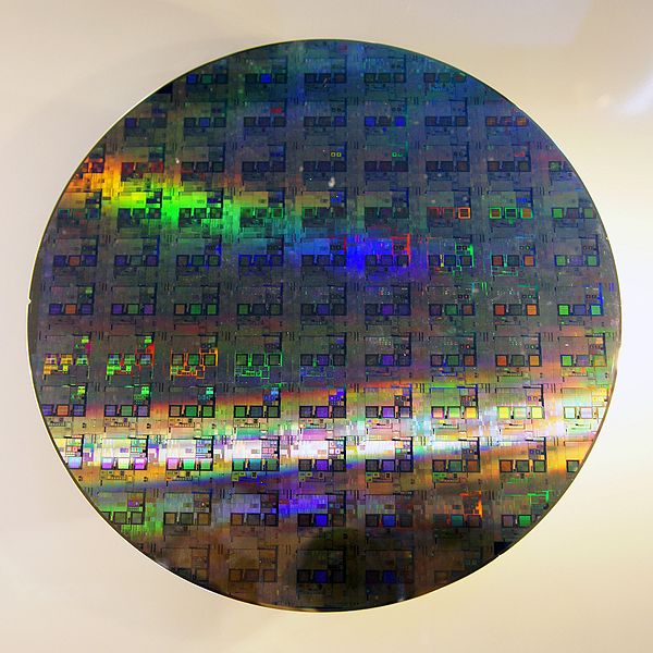
… as an aside – did you ever wonder why they are always round? Turns out the silicon crystal is “grown” from a seed and becomes one of these beasts – and the wafers are sliced out of it:

Sorry – got a little distracted – back to our switches.
So… its a switch… so what?
It turns out… with switches you can create “boolean logic”. Boolean logic is the sort of thinking that says “if this is true, then that is true”, or “if this and that and that or this and that and that or this and…” you get the point.
Before we get into logic though… with the transistor representing “on” and “off” for us, like a switch, we can say “on” = “true” and “off” = “false”.
States: on = true = high
For transistors “on” is the “high” state. Where “high” is the voltage present on the circuit that matches the battery’s voltage or the “sources” voltage. So… this is the first link between circuit, transistor and logic.
Lets say you are looking at a small circuit board – you can take your volt meter and probe any line in a digital circuit. If its voltage is non-zero that line is probably a logical “on = true = high = 1” and if the voltage is zero we say its “off = false = low = 0”. Typically that line is changing so fast you need an oscilloscope to see these fluctuations – but we’ll ignore that for now.
Looking at a transistor in “picture” – the simplest gate a “not”:
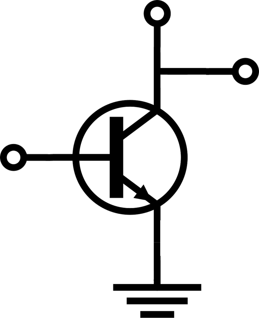
In this picture of a transistor (note this isn’t a MOSFET symbol but ignore that too for now) the “state” of the circuit comes in at the left-most circle. When that signal is positive the transistor is turned “on” allowing current to flow from the top circuit to the bottom… or in this case it “shorts” the source(the top circle) to ground.
This is actually the “not” gate. Meaning when a “high” signal is on that left-most circle, the reading at the farthest right circle is connected to “ground” or “zero” or “false”. When the signal at the left most circle is “zero” or “low” or “off” or “false” the switch is OFF which means the right most circuit will see “high” (because the electrons from the top are not running to the ground). Which means the output becomes the opposite of the input… a “not” or “nope”.
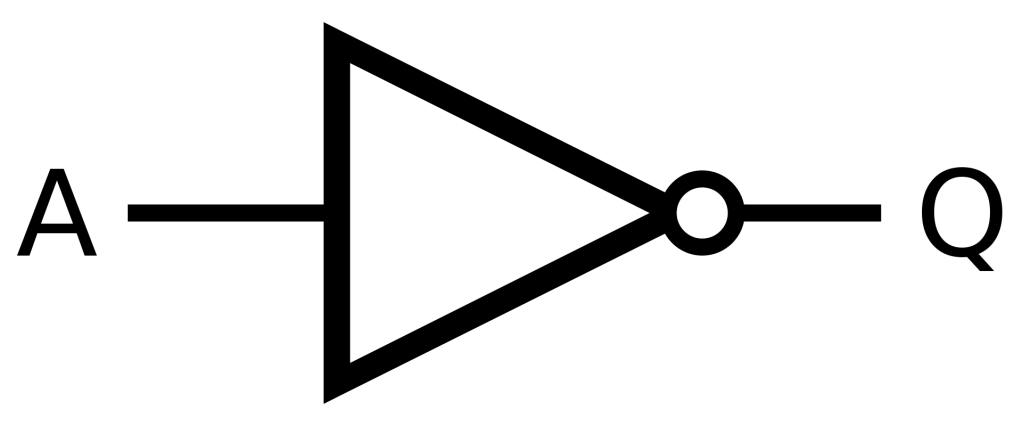
In boolean logic circuits – this is shown as this picture (A is the input, Q is the output):
Truth Tables … something to get familiar with.
The Truth Table is a handy way to think in terms of logic. This is the “truth” table of the “not” or “inverter” that we just saw. It should be pretty self explanatory here – but as we put together more complex “gates” we’ll need more complex truth tables.

What is this “gate” you speak of?
Ok… we should take a moment to talk about “gates” – all of these logic abstraction bits are called “gates”. The reason for that, I think, is that signals must “pass through” these like people pass through “gates” in fences.
Its kinda like every single one of these “logic” blocks is a test.
Ok… whoa – if you just understood what you read… take a moment…
If you understood the above paragraphs – you now understand more than 99% of the planet. To be clear… I know you don’t yet know how this pertains to computers… but rest assured – its ALL boolean logic. And in the next couple of articles I’m going to take you through “AND”, “OR”… and their brethren “NAND”, “NOR”.
For now though… sit back and lock in your knowledge.
Revel in the secret…
I sell a shirt over at Amazon that is only for those in the know. Flaunt your knowledge if you like (it comes in lots of colors):
Then later… this will all make sense.