


For a little servo background…
See my article on the servo-trigger:
Servo Triggers – Quickest, Fastest, Easiest way to make your servos dance
To install node…
See my NodeJS installation article:
Installing NodeJS on a Raspberry PI
Then… a little something on PWM
Ok, a little background: Controlling servos works by using something called PWM or Pulse Width Modulation. Servos have little computers in them that expect a signal that looks something like this:

So now imagine that a servo can turn 180 degrees. If the controller of the servo wishes for the servo to position itself at that full rotation of 180 that blue line, which represents the voltage on the raspberry pi’s pin, would be “high” the whole time. If it wanted to be at 0 degrees, that blue line would be “low” the whole time. Then for the values in between, that line is high for the fraction of 180 the angle represents. The “25% duty cycle”, is an example of the PI wishing to get the servo to go to: 180/4 = 45 degrees.
Now that is a waaaay short explanation. There is a better one from the folks over at Sparkfun:
https://learn.sparkfun.com/tutorials/pulse-width-modulation
Installing the software…
First, make sure you have git installed:
sudo apt-get install git
Then install the repo that contains the magic that is able to expose PWM to user-space (a term for lower permission access):
git clone https://github.com/richardghirst/PiBits.git
cd PiBits
cd ServoBlaster
cd user
make
sudo make install
That installs the servo driver software.
Next we’re going to install a little script to make interacting with that driver easy:
npm install pi-servo-blaster.js
Wiring up a servo… or lots of servos…

All servos have three wires:
- Ground – Black or Brown
- Power (usually 3-6V) – Red
- Signal – White, Orange, or Blue
The trouble with servos is that they draw lots of power. They are little motors that spin really fast, and gear up to drive with lots of force. Your PI cannot source that current through its pins because those pins are, in most cases, directly connected to microscopic wires or transistors inside the main chip. Those micro wires can only handle around 50ma – your servo needs upwards of 500ma!
Method 1: Tap into the power entering the PI
So you need to get right to the source of the power… before it gets to the chip. Like this:

Here you are taking the power straight from the power supply for the whole PI system. This works if there is enough amperage on your supply that isn’t yet used by the rest of your system.
In that image, the Black of the servo is soldered to the housing of the USB connector. The White(which is later connected to the servo red) is soldered to a point that is directly connected to the hot on the USB connector… at 5V.
See the video below to see the whole wiring harness in action.
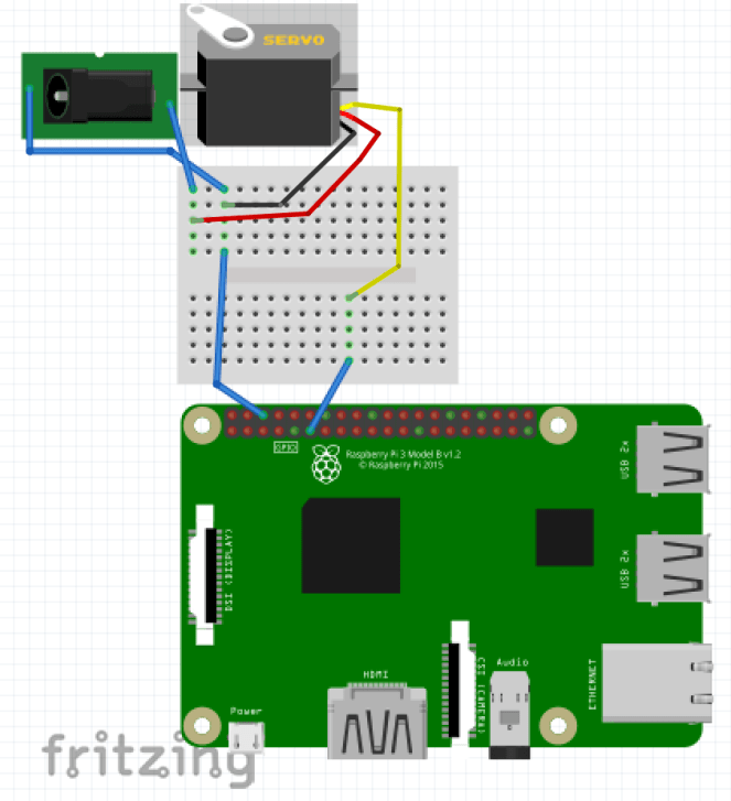
Method 2: Use a separate power supply.
The other, more reliable, method is to use a separate supply. When using this method – a crucial thing to keep in mind is the Grounds of the two systems must be tied together. To accomplish this, feel free to use one of the ground pins on the PI.
I will normally use something like this:

The standard size for most barrel connectors is 5.5mm, with an inside diameter of its pin is 2.5mm. There is a great overview article about barrel connectors here:
https://learn.sparkfun.com/tutorials/connector-basics/power-connectors
In any case, if you get yourself a couple of those – you’ll be able to use most of these:

https://www.adafruit.com/products/276
If you use the screw terminals in the above image, clamp two wires into the negative side, and use one of them to tie into the Raspberry PI’s Ground pin.
Take care to make sure the voltage you provide the servo is between 3V and 6V. Read the back of the power supply, it will have all the details. Also, just in case you get a weird one, check the polarity. It should have the picture seen here on the left.
 (Source: Sparkfun’s Article)
Finally, make sure it can provide enough current to the device. Each servo is different, but a simple one that is moving without load takes about 180ma. So there is probably a surge of up to 300, and if you put a load on the little guy, it could spike even higher.
For a good list of available servos and their specifications see:
https://www.servocity.com/servos/hitec-servos#standard
Wiring it up…
Note, this works for doing lots of servos too. In fact, the raspberry pi can control up to 8, the only other limit you’ll run into is that of your power supply.
Finally… some code!
This is a simple program to “sweep” the servo. ServoBlaster only gives you access to control the PWM duration. So, as you can see in the code, I wrote a tiny function that converts angle to PWM percentage.
Save this into: index.js
var piblaster = require('pi-servo-blaster.js');

function angleToPercent(angle) {
  return Math.floor((angle/180) * 100);
}

var curAngle = 0;
var direction = 1;
setInterval(() => {
  piblaster.setServoPwm("P1-11", angleToPercent(curAngle) + "%");
  console.log("Setting angle at: ", curAngle, angleToPercent(curAngle));
  curAngle += direction;
  // Change direction when it exceeds the max angle.
  if (curAngle >= 180) {
    direction = -1;
  } else if (curAngle <= 0) {
    direction = 1;
  }
}, 10);
For this to work, you should use the control pin which is on the left and six down from the top. Just like we did in the Fritzing up above.
In this case the pin is labeled 11, and GPIO17. Then notice the ground pin was tied into the barrel connector.
The run the code like this:
node index.js
You should see the servo sweep like this:
If you have trouble, add a comment and I’ll try to add more detail in the article for anything that gets in your way.
To find out more about this library – check out the author’s site:
https://github.com/richardghirst/PiBits/tree/master/ServoBlaster
The javascript library we use to interact with this – just writes to the FIFO file like his examples do.
Warnings!
First – some servos can be very strong. Please take care not to get pinched.
Second – power is going to be your next biggest gotcha. This article is about getting you around all that.
Third – this does not work on the PI Zero! Pi zero halted when I attempted to use this library… I haven’t tracked down why just yet.
Fourth – there are many different kinds of servos. Not all are 180 degree, some are 90, some are 360, some are continuous rotation. Each of these cases will need slightly different code in the angleToPercent function. Here is an example of that earlier code where the angle is a little easier to munge.
var piblaster = require('pi-servo-blaster.js');
const MAX_ANGLE = 180;
function angleToPercent(angle) {
  return Math.floor((angle/MAX_ANGLE) * 100);
}

var curAngle = 0;
var direction = 1;
setInterval(() => {
  piblaster.setServoPwm("P1-11", angleToPercent(curAngle) + "%");
  console.log("Setting angle at: ", curAngle, angleToPercent(curAngle));
  curAngle += direction;
  // Change direction when it exceeds the max angle.
  if (curAngle >= MAX_ANGLE) {
    direction = -1;
  } else if (curAngle <= 0) {
    direction = 1;
  }
}, 10);
If all of this fails…
There is hardware that can help. First, triggers like these:
Servo Triggers – Quickest, Fastest, Easiest way to make your servos dance
There are also boards that can help separate the power for you. This one from adafruit has some great tutorials.
https://www.adafruit.com/products/2327
And other tutorials:
https://learn.adafruit.com/adafruits-raspberry-pi-lesson-8-using-a-servo-motor?view=all
Have fun!
